A common misconception is that I spend a lot of my time "bendin' wood"....although it's possible, it's not very practical in most situations. There's usually a simple solution to most problems. All of these projects are in the back of my mind regardless of what I'm working on, and there might be several different way to go about it. My attitude is "I guess I'll figure it out when I get to that point".
Tubing or PVC is the most logical solution, and that's what I ended up using on the dragster. In the end it was the best way to go, however, bending plastic presents it own set of problems.
With the F/C I really wanted to use as much wood as possible, within reason. It's just a personal preference, but on the other hand I'll use whatever it takes to get the job done in the end.
After some trial and error, I settled on dowelrod. Each tube consisted of two separate pieces of wood. After both lengths were cut, a 45 degree angle was made on each end. A quick jig was built to ensure that all the tubes were exactly the same when glued up. After all 8 pieces were done, another vertical jig was built to drill the short end of the tube. This was quite tricky!

In hindsight, I should've drilled the ends before the two pieces were joined. After several test pieces, I was fairly confident I could drill them without screwing up the entire tube. Using a large Paddle Bit, each piece was drilled as deep as possible without breaking the thin tubing that remained. I decided that 1" was deep enough. A good jig was really important here as a little bit of slop would've been disastrous. After the drilling was complete, a layer of 5 min. epoxy was applied to strengthen the thin wall of the tube.
The next step was to create the curve in the bends. At this point the tube looks like a letter L. The outside corner was ground down to the determined radius, then the inside corner was filled with scrap wood and Bondo to complete the bend.....pretty simple huh?
Another jig was built to hold all the tubes in place to the shape of the final header. The short ends were glued together, and the long ends were marked to cut at the correct angle. The mounting plate was added last to make it a strong structure.
Bending PVC creates another set of problems, the worst being that the bend wants to collapse in on itself. After quite a bit of trial and error, I ended up putting a piece of large electrical wire inside the tube, heating it to the point of failure, then putting it in a jig while it was still hot. This works only if you can get the wire back out after its cooled down. Liquid dish soap turned out to be the best solution. Later on I read a technique were the tube is filled with sand, capped on both ends and then bent. Seems like it should work, but I haven't tried it yet. The rest of it was built basically like the F/C headers.
My next try will probably be a crazy set of collectors for the 34' coupe. The sand filled tube idea might work well in this situation.
 I dont think I can explain how I built the motor.......it's made completely from wood with a few exceptions.....I'm steady adding details to it, should be ready for paint before too long....

 Almost every piece is built to come apart for final finish, then reassembled..............................
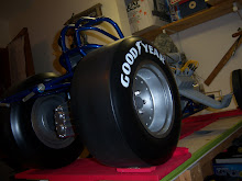
 Approximate size without the Headers: 14"t x 12"w x 12"l.....overall width is 28"


.jpg)


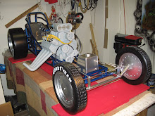
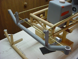 I built the front axle from wood as a mockup to give me some kind of idea what it would take to build it with the necessary structural integrity. After some trial and error, I settled on 3/4" steel tubing. Instead of trying to bend the tubing, it was much easier to cut all the pieces and then simply weld them together. All the welding on these parts was done by my buddy Bob, who, when he's not "shuckin' corn" is one of the best fabricators that I know.....
 The rear bracket was made from 1/4" brake line and was much more complicated. I built several jigs for theses parts because of the number of pieces that were required. The two side pieces were made first by laying all the parts in a jig and tack welding everything together. The finished pieces were then placed in another jig to add all of the cross bracing. Once I had a good solid structure, all the welds were ground and finished with bondo to achieve a very slick looking bracket with plenty of strength. After a few test fittings everything was primed and painted to match the chassis........
  Building the body was quite a project. I've never done anything like this before, and I really had no idea how to go about it. What I did know was that I would be able to build the sides flat and then temporarily connect them together with frame work that would later be removed. If I got that far I figured that I could add everything else to the initial frame work....maybe...
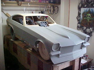
 I started with an outline of the side of the body, they were cut from 3/16 birch ply and clamped flat. My biggest obstacle was to create the horizontal body line. I laid a stringer the length of the body were the line should be. I then made another flat outline of the side and cut it down the center where the body line would be. These pieces were then glued over the stringer and to the first outline to form a shallow v shape that would create the body line. Once I had this shape, I was confident I could add the rest of the body.
 The two side panels were then held together with some basic framework to keep everything square while I built the rest of the body. Next came the front end and the hood. This was some pretty straight forward wood working. The front end was a lot of simple shapes added to a flat piece that held the front fenders together. The Hood was bent over some more temporary framework that would later be removed. The top of the fenders were boxed in next to tie everything together. These parts were really a lot of fun to make, I had no major problems, and the front end was looking good beyond my expectations.


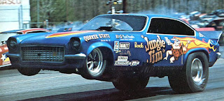

 This car is baddass, I like it a lot........I've noticed the bubbles on the front fenders of most of these cars, I plan on adding them to mine regardless of the final scheme, I could use the clearance. Since this is not an exact scale project, I'm kind of pickin' an choosin' what I like from a lot of different cars....

 I don't know much about this car......but I like it.....in the end I'll probably go with a scheme people will recognize......maybe..... comments are welcome.
 Basic construction started with a piece of 1" dowel rod. The main housing was several pieces of pine cut to a rough diameter and then slid onto the dowel and glued into place. The next step was to turn it on the lathe to get the correct size and taper. The front and rear housing were simple blocks that were added after the lathe work was complete.

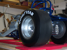
 The brackets that hold the housing in place are fairly simple parts. The first halve of the bracket slides onto the axle, the outside ring captures both the bracket and the mounting point on the frame. All of the major components are designed to come apart since the entire car is built and assembled first, then disassembled for Body and Paint work.

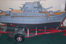
 First the Keel and the rest of the outline was


 My technique for joining all the pieces is very simple but quite effective. Each piece is cut to
  After the frame was completed, it was removed from the jig and all joints were reinforced with epoxy. Final finishing is quite time consuming. Every joint was ground, and then minor fill work with automotive
  now........where's my wood bender at??..........